
#note, if you do not have the diameter symbol in the feature control frame, you do not use “2*” in the formula. This statement is untrue, so this would indicate the part has failed for position by 0.028mm (0.128-0.1=0.028). Order of operations: Square each deviation first, then add the results, then square root that sum, then multiple that by 2. Leaving behind only the mathematical values now that they are related, we can now finish the equation as a test function: Then we need to set this solution equation equal to (or less than) the position tolerance and so: That equation will give you the radial deviation from nominal and it seems like we are done, but in order to solve position we are comparing our circle to the tolerance zone circle and the tolerance zone circle is in terms of diameter as indicated by the diameter symbol in front of the tolerance in the feature control frame, and yet our circle is in terms of radius, so we need to transform the solution into terms of diameter where radius is equal to diameter divided by 2: Start out by solving radial deviation since we have data in terms of x and y deviation and so we take the algebraic function for a circle and we solve for Δr We actually need the algebraic function of a circle, formula x^2 + y^2 = r^2, because our tolerance zone is a circle. The formula for finding the sides of a right triangle is a^2 + b^2 = c^2 and so it looks similar to what we need but it will not relate to the solution. Instead it is a calculation of how far our measured feature is from the nominal position of that feature on the print. To solve for position it must be noted that it is NOT Pythagorean theorem position is not a calculation of how far our feature is from zero, it is not finding the hypotenuse, thinking that will leave you curious about why we may multiply by 2 in the final equation. This value is always positive regardless of how you enter the numbers in subtraction so remove the negative now to make future calculations easier. The difference between the nominal distance and our measured distance is the deviation or change (Δ) in that direction. (yes, there are other ways to formulate this, but this one is fool proof in my opinion)Įxample nominal distances (given by basic dimensions or “boxed” dimensions on the print):

If the gage/equipment you are using in your measurement does not easily find the center, you can find the center of the feature by measuring the closest and furthest points of the feature and using the following equation:Ĭlosest point of the feature from the datum + ( / 2) = center point of the feature from the datum. Measuring these 2 distances while constrained to the surface datum-A- is all the information we need to check position, but please remember when measuring your x and y distances that it is the center of your feature that is needed. (note that both B and C control a linear position, but since B is before, or more important than, C, if these 2 sides are not perpendicular then error is said to be in C as the angular/rotational alignment is assigned to B).

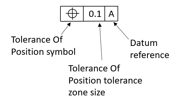
It is an outside edge which gives us a linear distance from the feature to the datum let us call this our “x” value.ĭatum-C-, our tertiary datum, is another outside edge, one that is perpendicular to datum-B-, it gives us another linear distance from feature to datum let us call this our “y” value. Often this means we should check position from both ends of the hole, as a CMM program will give the worst end of the hole as a result.ĭatum-B- is the secondary datum. This tells us that we are to constrain the part to datum-A- while checking these positions, and if they (the cylinders we call holes) are not perpendicular to the plane, this may create some unwanted error in our measurement and the function of the part. In this case, the primary datum, datum-A-, is the top plane/surface of the part and the holes/bores being checked for position are perpendicular to datum-A. You are finding the position by measurement as compared to the true position this is a position call-out. You are not finding the true position this is not a true position call-out. True position is the position of that feature without any deviation, or the perfect position as it pertains to the print or CAD model. This feature control frame does not call-out True position. The image is an example of a common feature control frame (called out to holes on a flat rectangular plate):įirst, let’s address the term “True Position”.


 0 kommentar(er)
